


 +86 152 6060 5085
 English
 русский
 español
 português
 العربية
 Polski
- Home
- Products
- News
- Blog
- About Us
- Contact Us

Blog
Catalog
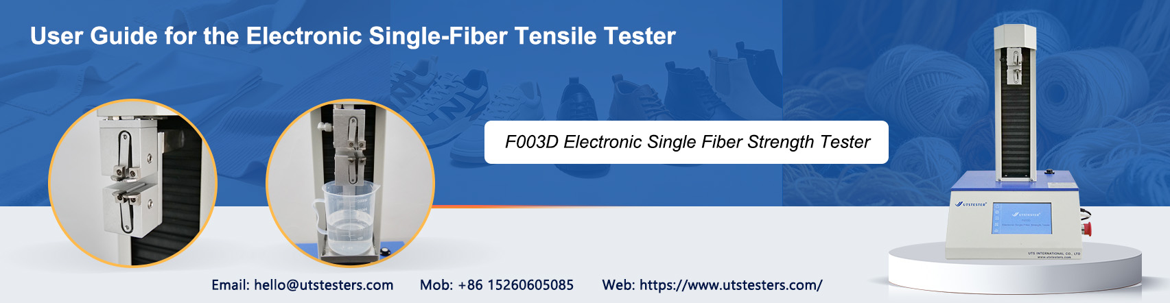
In the fields of textile material research and development and quality control, the electronic single-fiber tensile tester is a specialized instrument used to measure the breaking strength and elongation at break of fibers. It is widely used for performance testing of materials such as cotton, wool, linen, silk, chemical fibers, and glass fibers. This document provides a systematic introduction to the instrument’s operating procedures, key parameter settings, and daily maintenance techniques.
I. Working Principle and Structural Overview
The electronic single-fiber strength tester is a constant rate of extension (CRE) tensile testing instrument. Its operating principle is as follows: a high-sensitivity sensor converts the force exerted on the fiber during stretching into an electrical signal. After amplification and analog-to-digital conversion, the breaking load value is displayed directly in digital form. Simultaneously, a stepper motor drives the lower grip to move at a constant speed, while a microprocessor records the number of pulses and performs a scaling transformation to calculate the fiber’s elongation at break in real time.
Modern electronic single-fiber tensile testers typically consist of three components: the main unit (including the force sensor, transmission mechanism, and grips), the operating control system (touchscreen panel or online software), and the data output module (printer or computer interface). Gripping methods include manual, pneumatic, and electric gripping. Among these, pneumatic gripping effectively reduces human interference, making testing more objective and efficient.
II. Preparations Before Testing
1. Checking the Environment and Instrument Condition
Testing should be conducted under standard atmospheric conditions, i.e., at a temperature of 20±2°C and a relative humidity of 65%±2%.
The following checks must be completed before the experiment:
- Use a spirit level to adjust the instrument base to ensure the entire unit is level and stable
- Clean dust from the workbench and instrument surfaces, paying particular attention to the test probes and sensor probe areas
- Check whether the jaws of the upper and lower clamps are flat and free of wear; replace the jaw spacers if necessary
- Confirm that the power supply voltage is stable at AC 220 V ± 10%, with a frequency of 50 Hz
2. Sample Pretreatment
Fiber samples must undergo moisture equilibration prior to testing. Place the sample in a standard atmospheric environment for at least 24 hours to allow it to reach moisture equilibrium. If the sample’s moisture regain exceeds the standard moisture regain, pre-conditioning must be performed first (at a temperature not exceeding 50°C and relative humidity of 10%–25%) before moisture equilibration.
When sampling, randomly select approximately 1,500–2,000 fibers from the laboratory sample. Gently pull and straighten them several times by hand to ensure one end is even and straight, then randomly select a single fiber from the bundle for testing. Take care to avoid damaging, bending, or contaminating the fibers during this process.
3. Power On and Preheat
After connecting the power supply, the instrument must preheat for 30 minutes to allow the internal circuitry and sensors to reach a stable operating state. Parameter settings and sample preparation can be performed during the preheating period to improve testing efficiency.
III. Detailed Explanation of Core Parameter Settings
The appropriateness of parameter settings directly determines the accuracy and comparability of test results. The following are several key parameters that require special attention:
Clamping Distance (Spacing Length)
The clamping distance should be determined based on the average fiber length:
- When the average fiber length is less than 35 mm, set the clamping distance to 10 mm
- When the average fiber length is greater than 35 mm, set the clamping distance to 20 mm
Some newer instruments support arbitrary gap settings within a range of 560 mm, and the instrument can automatically locate the position, significantly improving operational efficiency.
Pre-tension
The purpose of pre-tension is to keep the fiber straight but not under tension prior to testing. Different fibers have corresponding standard values:
- Cotton fibers: 0.2 cN/tex
- Synthetic fibers (e.g., polyester, acrylic): 0.75 cN/tex
- Other fibers (e.g., wool, hemp, silk): 0.5 cN/tex
If the pre-tension is too low, the fiber may be initially bent, resulting in an overestimated elongation; if too high, it may prematurely damage the fiber, leading to an underestimated breaking strength.
Tensile Speed
The setting of the tensile speed is closely related to the fiber’s elongation at break and follows the following principles:
- Elongation at break E < 8% (low-elongation fibers, such as ramie): Tensile speed is 50% of the nominal gauge length per minute
- Elongation at break 8% < E < 50% (medium-elongation fibers, such as cotton and polyester): Tensile speed is 100% of the nominal gauge length per minute
- Elongation at break E > 50% (high-elongation fibers, such as spandex): Tensile speed is 200% of the nominal gauge length per minute
IV. Standard Operating Procedure
Step 1: Access the Parameter Settings Interface
After the instrument has finished warming up, access the main menu or the online software interface. Set the following parameters in sequence: specimen name, linear density, pre-tension, grip distance, tensile speed, load range, number of tests, etc. Save the settings after verifying they are correct.
Step 2: Instrument Calibration and Zeroing
Execute the “Reset” operation to return the lower clamp to its initial position. Use standard weights to calibrate the force measurement (some newer instruments support an automatic calibration procedure, which completes precise linear calibration in just three steps). Then perform the “Tare/Zero” operation to ensure the force display reads zero.
Step 3: Sample Clamping
1. Use tweezers to pick up a single fiber from the felt pad and check that its surface has no obvious defects.
2. Place the upper end of the fiber into the upper clamp and gently tighten the screw to secure it (for pneumatic clamping, press the clamping button).
3. Attach the pre-tension clamp to the lower end of the fiber so that the fiber is naturally straightened.
4. Place the lower end of the fiber into the lower clamp and tighten to secure it.
5. Confirm that the fiber is centered between the upper and lower clamps, with no skewing or tangling
Step 4: Start the Test
After confirming that the specimen is clamped correctly, press the “Test” or “Start” button. The lower clamp descends at a set speed, gradually stretching the fiber. The instrument collects force and elongation data in real time and dynamically displays the tensile curve on the screen.
When the fiber breaks, the lower clamp automatically stops and returns to its initial position. The interface then displays data for this test, including breaking strength, elongation at break, elongation percentage, and break time. Some instruments can also automatically calculate and display derived metrics such as breaking energy and initial modulus.
Step 5: Repeat Testing and Data Management
Test the remaining specimens in sequence according to the steps above. Modern electronic single-fiber tensile testers typically feature automatic statistical functions that can calculate maximum, minimum, and average values, as well as the coefficient of variation (CV), in real time.
After testing is complete, data can be exported in Word, Excel, or TXT formats for subsequent quality analysis and archiving. Some high-end models support the export of test curves and data sampling points, facilitating in-depth analysis using professional software such as Origin.
V. Calculation of Test Results and Interpretation of Indicators
Key Test Indicators
- Breaking force: The maximum load a fiber can withstand before breaking, measured in centinewtons (cN)
- Breaking strength: The ratio of breaking force to linear density, measured in cN/dtex; this is a core indicator for evaluating fiber strength
- Elongation at Break: The percentage increase in length relative to the original clamped length when the fiber breaks, reflecting the fiber’s elasticity
- Work at Break: The work done by the external force on the fiber during tensile testing, reflecting the fiber’s toughness
- Initial Modulus: The slope of the initial linear segment of the stress-strain curve, reflecting the fiber’s stiffness
Calculation Formulas
Average breaking strength = Σ(breaking force) / linear density (cN/dtex)
Elongation at break = (elongation at break / clamping length) × 100%
The reliability of test results can be assessed using the coefficient of variation (CV value). Generally, a CV value of 10%–15% for breaking force is considered within the normal range. If the CV value is too high, check the representativeness of the sample, the standardization of the clamping procedure, or the uniformity of the fiber itself.
VI. Common Issues and Solutions
Clamping Slip
Symptoms: Irregular fluctuations appear in the tensile curve before reaching the peak, or the break occurs at the clamping point rather than in the middle of the fiber.
Causes and Countermeasures:
- Insufficient clamping force: Tighten the clamping screws appropriately, or check the pneumatic system pressure
- Worn jaws: Replace the jaw pads; it is recommended to use specialized jaws with a fine-textured surface
- Excessive pre-tension: Recheck and adjust the pre-tension value
High Data Variability
Symptoms: Significant fluctuations in test results for the same batch of fibers, with a high CV value.
Causes and Solutions:
- Non-representative sampling: Increase the sample size to ensure the sample covers the entire batch of fibers
- Inhomogeneity of the fibers themselves: This is a normal phenomenon; random errors can be reduced by increasing the number of tests
- Inconsistent operating procedures: Strengthen operator training to standardize clamping force and speed
Sensor Drift
Symptoms: The force reading is not zero under no-load conditions, or test values exhibit systematic deviations after calibration.
Causes and Countermeasures:
- Insufficient warm-up time: Ensure a warm-up period of at least 30 minutes
- Environmental vibration interference: Place the instrument on a stable laboratory bench, away from vibration sources
- Sensor aging: Contact the manufacturer for professional calibration or sensor replacement
VII. Applicable Standards and Specifications
Testing methods for electronic single-fiber tensile testers must strictly adhere to relevant standards, primarily including:
- GB/T 9997-1988 “Determination of Breaking Strength and Elongation at Break of Single Chemical Fiber”
- GB/T 14337 “Test Methods for Tensile Properties of Short Chemical Fibers”
- GB/T 4711-1984 “Test Methods for Breaking Strength and Elongation of Single Wool Fibers”
- ISO 5079 “Textile fibers—Determination of breaking strength and elongation at break of single fibers”
- ISO 11566 “Carbon fibers—Determination of tensile properties of monofilament specimens”
- FZ/T 50006, FZ/T 50007 (relevant standards for the chemical fiber industry)
Email: hello@utstesters.com
Direct: + 86 152 6060 5085
Tel: +86-596-7686689
Web: www.utstesters.com

Room 312, Block D, Jiayuan Garden, No.2 Zhongfa Road, Zhangzhou City, Fujian Province, China

+86 152 6060 5085

+86 596 7686689


 hello@utstesters.com
 hello@utstesters.com
 +86 152 6060 5085
 +8615260605085